Assembly instructions.
Introduction.
Thank you for purchasing the GRIN One. Please follow the instructions below to assemble the unit.
Notes.
This product is compatible with Cherry MX compatible switches. Keycaps are compatible with sizes 18x18 mm and smaller.
Slipping may occur depending on the combination of keycaps and switches. Compatibility of keycaps and switches is not guaranteed.
Acrylic plates and painted bumpers can become dull or cracked if cleaned with alcohol or other chemicals.
The 3D printed case is stained black and may cause colour migration if rubbed.
If you have any questions during assembly, please send us a message using the email icon at the bottom of the top page of the store website.
Work description.
1. Preliminary preparations
2. Check that the following items are included
3. Initial operation check
4. Paste form
5. Attaching the stabilisers
6. Installation of the MOD kit
7. Plate screw fixing
8. Switch and key cap installation
9. Bush installation
10. Case screwing
11. Firmware
1. Preliminary preparations
Prepare switch and keycap.
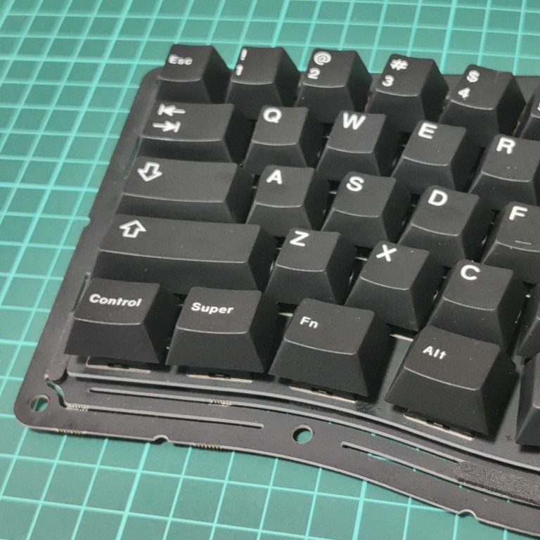
! Layout
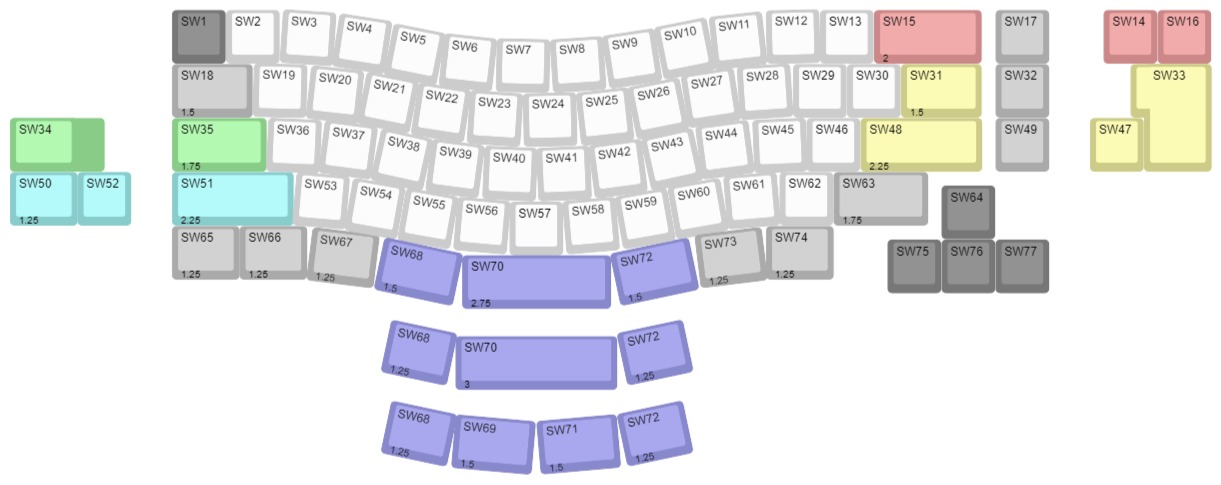
Decide on the key layout with reference to the diagram and prepare the required number of switches and keycaps.
SW15, SW33, SW48, SW51 and SW70 require stabilisers. SW70 also requires stabilisers for 3U; the MOD kit includes wires for 3U.
Prepare keycaps and the required number of switches and stabilisers, lubricate the switches and stabilisers if necessary.
Prepare tools.
- Phillips screwdriver (No. 1)
- Tweezers
- Scissors
- Paper rag or tissue etc.
2. Check that the following items are included
Please check that the following items are included. If any of these items are missing, please send us a message via the email icon at the top of the shop website.
Bag 1.
- Pre-soldered boards (including XIAO RP2040 and Cherry MX compatible sockets)
- FR-4 switch plate
Bag 2.
- M2 3.5mm spacers … 4 pcs.
- M2 3mm screws … 8 pcs.
- M2 6 mm screws … 2 pcs.
- Plastic washers (red, white and blue) … 9 each
- Rubber washers … 18 pcs.
- Poron gasket foam
- Rubber feet
- Stabiliser shims (for 1.6mm) …8 pcs.
- Magnets … 6 pcs.
- Round double-sided tape … 6 pcs.
The following are temporarily assembled.
- Top plate (matt black acrylic)
- Upper case (3D printed)
- Bottom case (3D printed)
- Bumper plate (copper, brass, stainless steel, acrylic)
- Bottom plate (copper, brass, stainless steel, acrylic)
- M2.6 screws 14 mm … 9 pcs.
- M2 screws 4 mm … 7 pcs.
- Metal bushings … 9 pcs.
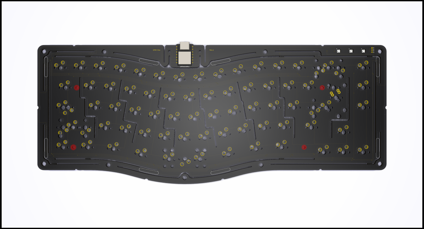
3. Initial operation check
Remove the soldered board from the bag.
The board is shipped with the firmware already written to check operation. First check that it works properly.
Connect to a PC and check that it is recognised.
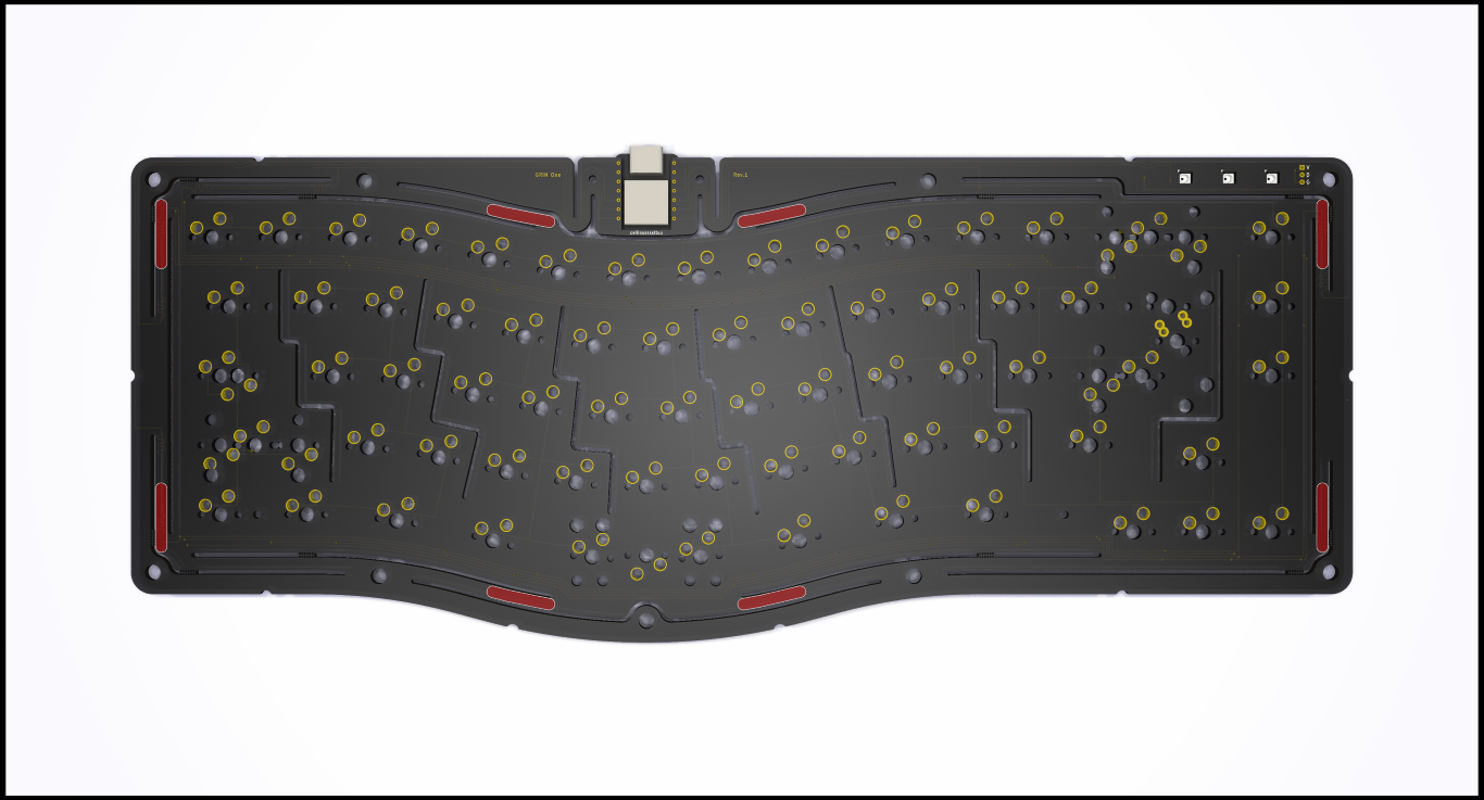
Short-circuit the terminals with tweezers, etc., and confirm that input is received.
Short-circuit the two points in the picture with tweezers or other conductors and confirm that the characters are input. If the text is not entered, please send us a message via the email icon at the bottom of the store website top page.
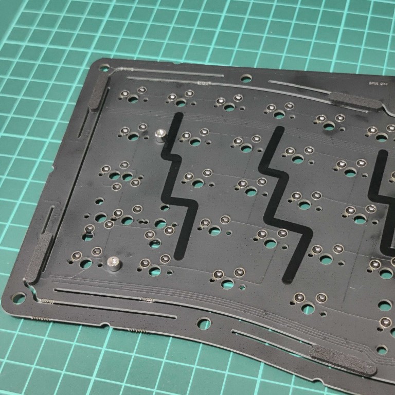
4. Paste form.
Gasket form.
Paste the gasket form in the position marked on the board.
! plate screwed down
5. Attaching the stabilisers
Attach the required stabilisers to the board. The board is 1.2 mm thick, so either install the supplied shims or use stabilisers for 1.2 mm thickness.
6. Installation of the MOD kit
If you have purchased a mod kit, install it at this time. It is also recommended to install the MOD kit after assembling without the MOD kit and enjoy the difference.
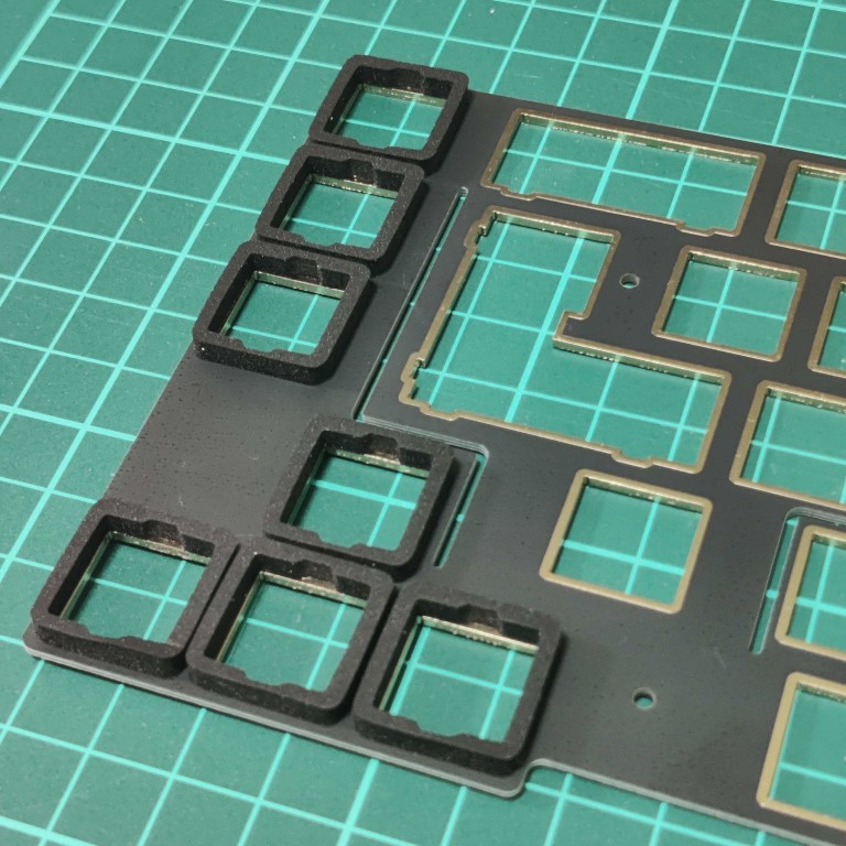
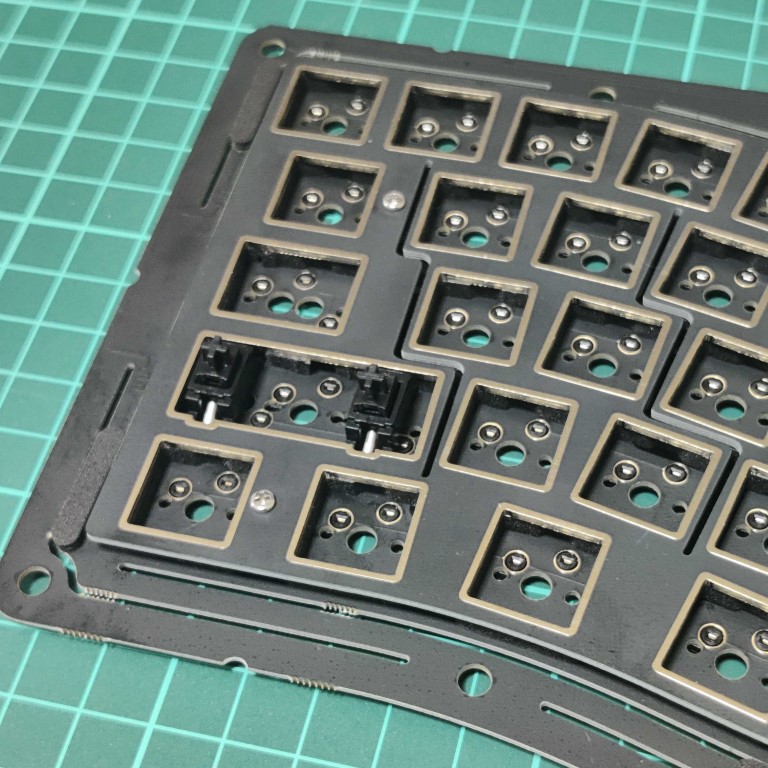
Switch foam
Attach the switch foam to the back of the switch plate. It muffles unnecessary noise generated by the switch.
When peeling the foam from the blue sheet, use pointed tweezers to carefully peel off the foam as the adhesive surface and sponge can easily tear off.
The part where the stabiliser attaches cannot be stuck as it is, so please cut out the part that gets in the way with scissors etc. and stick it on.
! Switch form
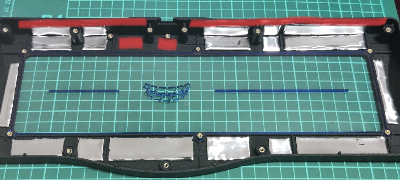
Butyl rubber mod.
Attach aluminium butyl tape to the board and case. It suppresses unnecessary resonance and has a silent effect.
You can cut it out with scissors and stick it freely, but do not stick the red part as it interferes with the PCB.
If butyl rubber sticks to the surrounding area, it cannot be removed. It is recommended to cover the surrounding area with newspaper, etc., before working.
Use alcohol to remove butyl rubber from your hands or scissors.
! Butyl rubber mod
Example of sticking position.
Flex cut tape mod.
By sticking it to the slit part of the board, the sound of the keystroke is emphasised and the reverberation sound inside the case is prevented from leaking out, making the sound of the keystroke clearer.
! Flex cut tape MOD
7. Plate screw fixing
Attach the board and switch plate with M2 3.5 mm spacers and M2 3 mm screws.
! Plate Screw Fixing
! Plate screw fixing !
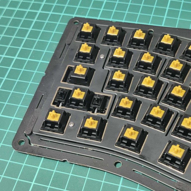
8. Switch and key cap installation
Install the switches and keycaps. This keyboard is a hot-swap socket, so switches can be replaced even after assembly, but be sure to replace the leaf spring mounts with the board removed, as they may break if strong external force is applied.
! Switch
! Key cap !
9. Bush installation
The bushings are assembled to the case when shipped. Remove the screws once. Be careful not to lose any small parts. If you lose them, please use spare parts.
! Bush
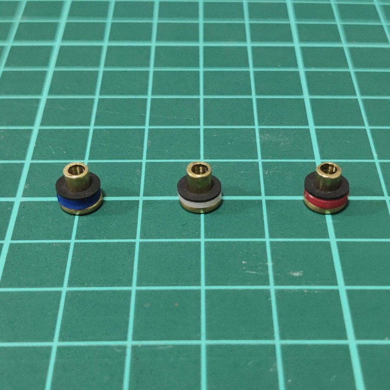
Install the plastic washer and rubber washer on the brass bush. The combination of plastic washers to be fitted here changes the feel of the keystroke.
Blue: soft, white: medium, red: hard; it is not recommended to insert more than two plastic washers here.
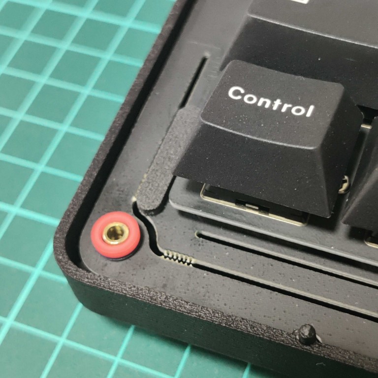
Place the bush in the bottom case.
Place the PCB on top of the bushing.
! bush
Place the rubber washers and the remaining coloured plastic washers on top of the PCB.
*One plastic washer of each of the three colours will be stuck in each bush.
10. Case screwing
Position the bumper, then the upper case, taking care not to dislodge the plastic washer from the bush.
Screw in the screws. Insert M2.6 14 mm screws in all places first and turn lightly. When all the screws have been inserted, retighten them evenly in the order of the numbers in the photo. Tightening too hard may cause damage. As a guide, retighten the screws by +15° from the point where they can no longer be turned with the previous force after turning them lightly. Due to the fact that the case is manufactured using a 3D printer, there may be some distortion in the case, so be sure to follow the above procedure.
Screw the upper case and bumper together with M2 3 mm screws.
Notes
The rubber washers are likely to stick to the circuit board, so if you remove the circuit board carelessly, the washers may fly off and cause loss. Carefully remove the board while peeling off the stuck rubber washers. If you lose it, use a spare part.
Attach the magnets to the upper case in six places. Attach a small piece of double-sided tape to the upper side of the magnets and then attach the top plate on top.
If the gap between the upper case and the top plate is large, the upper case is distorted and the screw fixing positions should be fine-tuned.
11. Firmware
The QMK/VIA-compatible firmware is included in the initial state.
The VIA JSON file is here.
If you need the uf2 file, download it from here.
The QMK source code is here.
The source code for Vial is here.